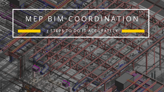
MEP BIM Coordination – 5 Steps to do it accurately

As the Architecture, Engineering, and Construction (AEC) industry face enormous pressure to deliver projects within stringent deliveries, enhancing process proficiency and decreasing rework is a prerequisite. One of the basic factors that adversely affect the productivity, profitability and on-time deliveries is the design and construction-related rework.
In addition, it impacts architects, subcontractors, MEP (M&E) specialists, consultants and the whole downstream chain. In comparatively bigger and more complex undertakings, the rework due to faulty design can adversely impact the whole workflow, delay project delivery and cost more than what was initially assessed.
Table of Contents
As mechanical, electrical, and plumbing (MEP) systems account for a significant portion of the project, the judicious use of Building Information Modeling (BIM) to effectively coordinate MEP systems reduces rework and increases productivity. The steps listed below will lead to a better MEP BIM coordinated model. Some of these may change based on the client/project requirement. However, it is essential to follow these stages in order to ensure better execution of the project and reap the benefits of MEP BIM coordination.
MEP BIM Coordination – How to Do it
#1 Review of Design Drawings
The first step to start the process of MEP BIM coordination is to review the single line design drawings. These include checking the Architectural and Structural plans in detail along with evaluating them for consistency with schematics. Then the MEP drawings and their specifications are studied based on which the coordination roadmap is laid out.
#2 Creating a 3D BIM Model
A 3D BIM model is creating based on the design drawings by using Revit software. This will include the MEP services created on the Architectural and Structural framework of the building. This forms the basis for several other important construction-related drawing sets. Additionally, this model can also be utilized to create renderings and walk-throughs.
#3 Coordination and Clash Detection
Once the 3D model is created, it is then evaluated for conflicts and clashes between the architectural elements and the MEP systems using Navisworks. It is a special software application that detects all clashes that are present in the model. These are then resolved by making the necessary changes. The final model will be free of any coordination issues and is deemed fit for the next stage.
#4 Creation of Drawings
The next stage is the preparation of various drawings based on the coordinated model. These include:
Coordinated Drawings and Sections
Coordinated drawing sets include mechanical, electrical, plumbing and fire protection systems in the same space. Additional notes can be added to bring more clarity to each service. These drawings form a base for the individual service drawings.
Detailed Service Drawings
Individual service drawings are created and details such as the sizes of the components, heights and distances from the gridlines, etc. are added for further clarity. These drawings serve as an input for the next stage of drawings i.e. the fabrication drawings.
Fabrication, Spool and Hangar Drawings
Individual service drawings as used to create fabrication drawings. This can either be done using traditional detailing techniques or use the FAB-MEP software. These drawings show the details that are directly recognized by the CNC machines for production purposes.
#5 As-built Changes
The final stage involves making necessary modifications based on site-based changes. The changes are applied to the model as well as the drawings. These changes can be minimized by efficient execution of coordination and following correct installations based on the construction drawing instructions and layouts.