How to execute MEP Coordination Modeling?
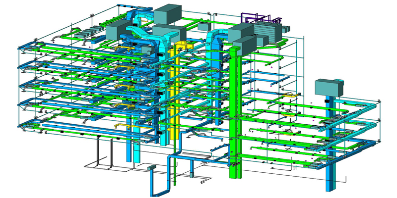
The MEP coordination method is used for developing 3D coordination models where all Mechanical (HVAC), Electrical and Plumbing components are integrated effectively. This method assists in reducing conflicts among these MEP components.
MEP coordination modeling is one of the crucial phases of MEP services as well as BIM services. Coordinating all the MEP components in a proper way is not an easy task. So, Modelers need to be very attentive while they generate coordination models because any small mistake can make a big loss of time and money.
MEP 3D coordination modeling ensures that all the MEP components do not make any kind of interference with other construction components i.e. building’s architectural design and structural components. The introduction of different advanced software like Revit, AutoCAD, etc. has eased the workloads of Modelers, Architects, and Engineers to some extent. Various companies execute this modeling process in various ways that depend on the project demands and level of detail (LOD). BIM Services India is a leading CAD & BIM services firm based in the US having expertise in developing MEP coordination models accurately.
In our company, we execute MEP coordination 3D modeling process in the following ways:
• Evaluation of Architectural, Structural & MEP design and Drawings – At first, our highly qualified and skilled Architects, Modelers & Engineers analyze MEP system layout drawings, Architectural drawings and Structural drawings thoroughly. After that, they decide how the coordination model will be made.
• Model creation – In this step, we create a highly effective coordination model using AutoCAD or Revit. Once the model is completely developed, we minutely check whether all the MEP elements i.e. HVAC, Electrical & Plumbing members have been properly integrated within the model or not. We also verify whether this model is in sync with building a structural model or not.
• Clash detection – after completing the above step, we evaluate the coordination meticulously for detecting clashes among the MEP components. If we notice any chance of conflicts such as design-related clashes, workflow clashes, or clearance clashes, we instantly fix the errors.
• Coordination drawing sets making – In this step, we prepare coordinated drawings from the 3D models. These coordination sets provide information about the sizes of the MEP members and assist our clients to understand how all the components have been integrated together within the allocated space. We also create elevation and section views of 3D coordination models.
• Creation of Service drawing – We prepare service drawings that include detailed information about components sizes & heights and distances from gridlines. Once the service drawing creation is completed, it is sent to the site installation team.
• Fabrication drawing creation – At this step, we create fabrication drawings that show fabrication details of the entire MEP system and its related members, e.g. HVAC duct, piping system, fire protection system, electrical system, etc.
• As-built drawings creation – This is the last step and in this step, we create as-built drawings which include information regarding all types of modifications that are performed in 3D models, site-based changes and differences from the construction drawings.
The computerized MEP coordination modeling process helps Modelers as well as Engineers in producing highly precise 3D coordination models within a quick turnaround time. This method assists in improving building design & quality and reducing time and project costs. This 3D modeling process is utilized for constructing a low-rise building to high rise and complicated building structure. MEP coordination is very important to make a building physically powerful and stable.